
 |
|
|
|
 |
 |
 |
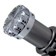
HPC milling cutters for finish machining |
| The chip guiding elements are mounted ex works! | |
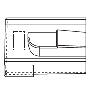
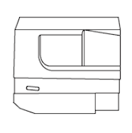
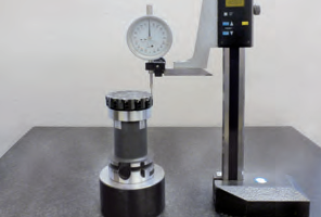
| 1. Determine the highest chip guiding element. Recommendation: Place milling cutter in a setting fixture and rotate under the dial test indicator and measure the individual guiding elements. 2. Assemble the milling cutter and tighten the clamping screws (CS 1) to 15 Ncm. Do not tighten the clamping screws (CS 2)! 3. Adjust the inserts in longitudinal direction with the adjustment screws (AS) to 10 μm before the setting dimension. Setting dimension = chip guiding element height +30 μm The maximum axial run-out error should be 2 μm. |
 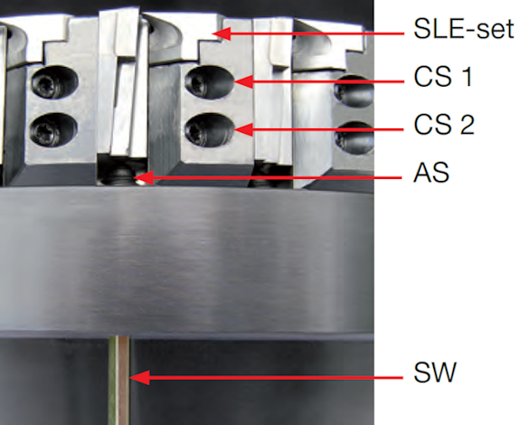 |
| 4. Tighten the clamping screws (CS 2) to 80 Ncm, loosen again and tighten to 15 Ncm. 5. Tighten the clamping screws (CS 1) to 80 Ncm. 6. Adjust all the inserts to the setting dimension. The maximum axial run-out error should be 2 μm. Tighten the clamping screws (CS 2) to 80 Ncm. 7. A check measurement is to be carried out after 10 minutes. If the axial run-out error is in excess of 2 μm, the inserts must be re-adjusted without loosening the clamping screws. |
|
| Torque (Ncm) | Torx size | Part nr. | Code | |
| Torque wrench fixed | 15 | Tx 6 | 20063 | 0.150 |
| Torque wrench fixed | 80 | Tx 6 | 20063 | 0.800 |
| Bit 6 for clamping screws CS1 / CS2 | 80 | Tx 6 | 4917 | 6.000 |
| Bit 8 for clamping element | 80 | Tx 8 | 4917 | 8.000 |
| Bit 6 interchangeable blade | 15 | Tx 6 | 20078 | 6.000 |
| Torque wrench adjustable | 10 - 80 | Tx 6 | 20063 | 0.810 |
| Spare Parts | ||||
| Tool type | Part nr. | Code | ||
| Q99... | Clamping screw | CS1&CS2 | 20080 | 3.000 |
| Adjusting screw | AS | 20081 | 4.000 | |
Safety note: In the event of damage the tool must be returned to the manufacturer for checking for technical safety reasons! Only original replacement parts must be used! |
 |
|
 |