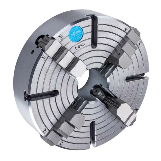
Independent Chucks
USE-USU  - individually adjustable jaws


APPLICATION
Clamping chucks for lathes on which large, heavy or irregularly
shaped workpieces are clamped.


TYPE
Independent 4-jaw chuck in steel design. Jaws individually
adjustable via threaded spindle (no central drive). Starting
from size 315 with T-slots.
Starting from size 1100 with T-slots and set-up slots.


CUSTOMER BENEFITS
• Concentric rings for visual rough centering, fine centering
  using dial gauge


TECHNICAL FEATURES
- Steel design incl. clamping wrench and fastening screws,
  as well as 1 set of reversible or base and top jaws


USE = individually adjustable jaws, steel, one-piece jaws

USU = individually adjustable jaws, steel, reversible top jaws


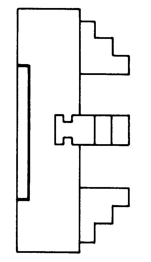
A26
Cylindrical centre mount (without mounting bolts)

 Size  With one-piece
 reversible jaws
 With base jaws
 and top jaws
 Through-hole mm  Speed
 max.
 min -1
 Torque
 Nm
 Clamping
 force/jaw
 kN
 260  139781▲  137147▲  70  2350  120  17
 310  139796▲  139720▲  75  1970  120  17
 400  139827▲  135368▲  95  1530  170  23
 450  139842▲  136944▲  95  1360  170  23
 500  139857▲  135631▲  95  1220  170  23
 630  139887▲  139723▲  135  970  240  37
 710  140800▲  141097▲  135  860  240  37
 800  140801▲  141106▲  190  765  300  45
▲  on request
Further sizes and mountings available on request

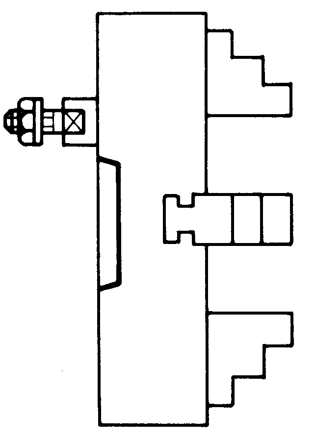
A26
ISO 702-3 (DIN 55027), DIN 55022, with studs and locknuts,
optional DIN 55021 with set screw and nut


 Size  Mount
 short
 taper
 With one-piece
 reversible jaws
 With base jaws
 and top jaws
 Through-hole mm  Speed
 max.
 min -1
 Torque
 Nm
 Clamping
 force/jaw
 kN
 260  4  139782▲  137163▲  61  2350  120  17
 260  5  139783▲  137164▲  70  2350  120  17
 260  6  139784▲  137165▲  70  2350  120  17
 310  5  139797▲  139724▲  75  1970  120  17
 310  6  139798▲  139725▲  75  1970  120  17
 310  8  139799▲  139726▲  75  1970  120  17
 400  6  139828▲  135371▲  95  1530  170  23
 400  8  139829▲  135372▲  95  1530  170  23
 400  11  139830▲  135358▲  95  1530  170  23
 450  6  139843▲  136947▲  95  1360  170  23
 450  8  139844▲  136948▲  95  1360  170  23
 450  11  139845▲  136957▲  95  1360  170  23
 500  6  139858▲  135632▲  95  1220  170  23
 500  8  139859▲  135633▲  95  1220  170  23
 500  11  139860▲  135696▲  95  1220  170  23
 630  8  139888▲  139767▲  136  970  240  37
 630  11  139889▲  139768▲  136  970  240  37
 630  15  139890▲  139769▲  136  970  240  37
 710  8  141088▲  141098▲  136  860  240  37
 710  11  141089▲  141099▲  136  860  240  37
 800  8  141092▲  600638▲  200  765  300  45
 800  11  141093▲  141107▲  192  765  300  45
 800  15  141094▲  141108▲  192  765  300  45
 900  11  -  600639▲  190  680  300  45
 900  15  -  600641▲  190  680  300  45
 1000  11  -  141115▲  190  610  320  47
 1000  15  -  141116▲  190  610  320  47
 1000  20  -  600645▲  190  610  320  47
 1100  11  -  150500▲  190  555  320  47
 1100  15  -  600642▲  190  555  320  47
 1100  20  -  600646▲  190  555  320  47
 1200  11  -  150501▲  190  510  450  64
 1200  15  -  600643▲  190  510  450  64
 1200  20  -  600647▲  190  510  450  64
▲  on request
Further sizes and mountings available on request

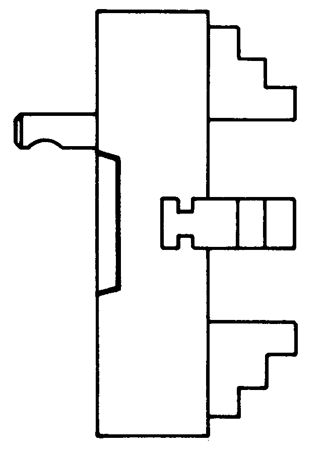
A26
ISO 702-2 (DIN 55029), ASA B 5.9, type D, with studs for Camlock

 Size  Mount
 short
 taper
 With one-piece
 reversible jaws
 With base jaws
 and top jaws
 Through-hole mm  Speed
 max.
 min -1
 Torque
 Nm
 Clamping
 force/jaw
 kN
 260  4  139791▲  137166▲  60  2350  120  17
 260  5  139792▲  137254▲  70  2350  120  17
 260  6  139793▲  137255▲  70  2350  120  17
 310  5  139806▲  139733▲  75  1970  120  17
 310  6  139807▲  139734▲  75  1970  120  17
 310  8  139808▲  139735▲  75  1970  120  17
 400  6  139837▲  135375▲  95  1530  170  23
 400  8  139838▲  135376▲  95  1530  170  23
 400  11  139839▲  135359▲  95  1530  170  23
 450  6  139852▲  136951▲  95  1360  170  23
 450  8  139853▲  136952▲  95  1360  170  23
 450  11  139854▲  136955▲  95  1360  170  23
 500  6  139867▲  135703▲  95  1220  170  23
 500  8  139868▲  135704▲  95  1220  170  23
 500  11  139869▲  135705▲  95  1220  170  23
 630  8  139897▲  139776▲  136  970  240  37
 630  11  139898▲  139777▲  136  970  240  37
 630  15  139899▲  139778▲  136  970  240  37
 710  8  140804▲  141102▲  136  860  240  37
 710  11  140805▲  141103▲  136  860  240  37
 710  15  -  141418  136  860  240  37
 800  11  140810▲  141418▲  192  765  300  45
 800  15  140811▲  141112  192  765  300  45
 900  11  -  600660▲  190  680  300  45
 900  15  -  600661▲  190  680  300  45
 1000  11  -  141119▲  190  610  320  47
 1000  15  -  141120▲  190  610  320  47
 1000  20  -  600665▲  190  610  320  47
 1100  11  -  150504▲  190  555  320  47
 1100  15  -  600662▲  190  555  320  47
 1100  20  -  600666▲  190  555  320  47
 1200  11  -  150505▲  190  510  450  64
 1200  15  -  600663▲  190  510  450  64
 1200  20  -  600667▲  190  510  450  64
▲  on request
Further sizes and mountings available on request


We reserve the right to make technical changes.