| The chip guiding elements are mounted ex works! |
 |
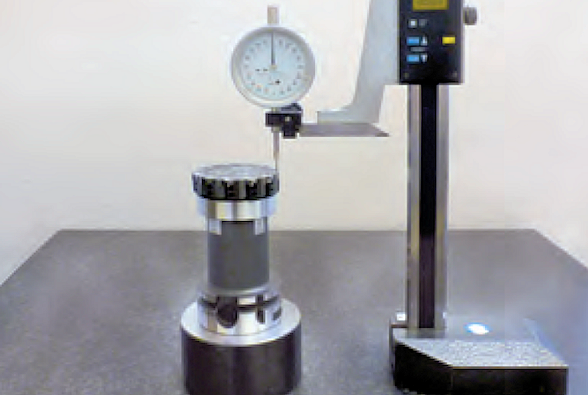
| 1. Determine the highest chip guiding element. |
| Recommendation: |
| Place milling cutter in a setting fixture and rotate |
| under the dial test indicator and measure the |
| individual guiding elements. |
| 2. Assemble the milling cutter and tighten the |
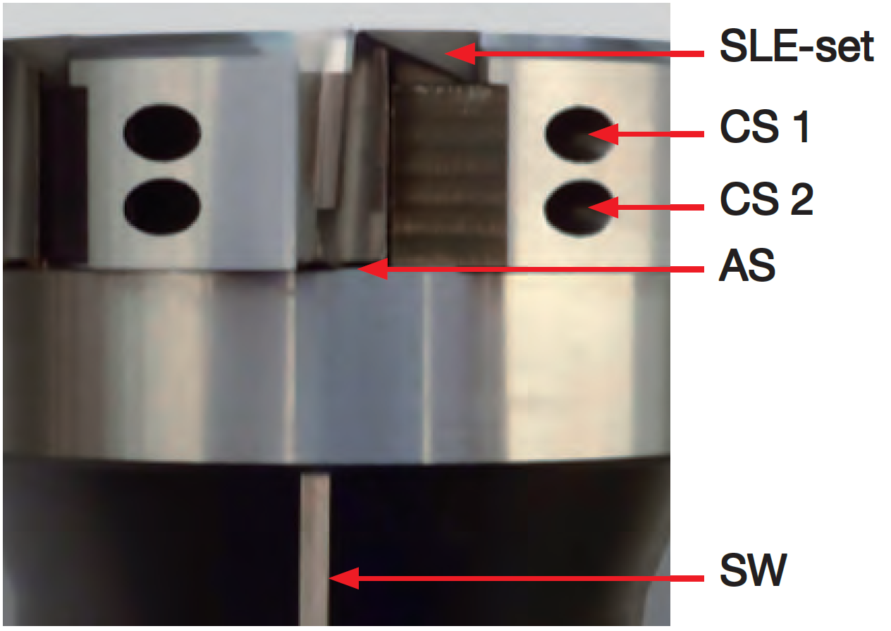
| clamping screws (CS 1) to 15 Ncm. |
| Do not tighten the clamping screws (CS 2)! |
| 3. Adjust the inserts in longitudinal direction |
| with the adjustment screws (AS) to 10 μm |
| before the setting dimension. |
Setting dimension = chip guiding element height + 0.1 mm |
| The maximum axial run-out error should be 2 μm. |
| 4. Tighten the clamping screws (CS 2) to 120 Ncm, loosen again and tighten to 15 Ncm. |
| 5. Tighten the clamping screws (CS 1) to 120 Ncm. |
| 6. Adjust all the inserts to the setting dimension. The maximum axial run-out error |
| should be 2 μm. Tighten the clamping screws (CS 2) to 120 Ncm. |

 maximum feed rates
 Inserts/Spare Parts (finish)
 Inserts/Spare Parts (rough)
 We reserve the right to make technical changes.